- This topic has 1 reply, 1 voice, and was last updated 5 years ago by
Hamid.
-
CreatorTopic
-
2021-08-03 at 11:08 am #279
NADER
I need three phase voltage, how can I obtain it? In my house we just access to one single phase counter as main power supply.
-
CreatorTopic
-
AuthorReplies
-
2021-08-03 at 11:08 am #1539
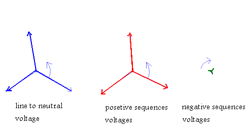
If you have an unused three phase induction motor (uncoupled mechanical), you can produce an approx three phase system by using of one single phase source. As you know an induction three-phase motor will RUN on only two of its three legs. Otherwise said, with single-phase power we can run a three-phase motor. The issue then becomes how to start said motor, because a three-phase motor will NOT START on single phase by itself. There are only two basic functions in starting and running a three-phase motor in static mode. 1. Switch single-phase power to two legs of the three-phase motor. 2. Connect the starting capacitor to the 3rd leg of the idler motor long enough for it to start, then remove it from the circuit. A momentary pushbutton, hand-operated by the user, can connect the capacitor just long enough to start the idler motor. In my case we can automate this process using a timed relay to connect the starting capacitor to the circuit then drop it out. Rotary conversion begins once a three-phase motor has been started and is running on single phase in static mode. Once running, if we measured all three voltages (L1-L2, L2-L3, and L1-L3) in the above diagram, after the motor is running, we’d find approx three AC phase voltage for each measurement. The points where we are measuring the three voltages is where three-phase power is now available! This is where to tie in the other machinery motors we want to run. Indeed, the phase converters provide 3-phase power from a single-phase source, and have been used for decades. The simplest type of old technology phase converter is generically called a static phase converter. This device typically consists of one or more capacitors and a relay to switch between the two capacitors once the motor has come up to speed. These units are comparatively inexpensive. They make use of the idea that a 3-phase motor can be started using a capacitor in series with the third terminal of the motor. It is almost guaranteed that a static phase converter will do a poor job of balancing the voltages on the motor. Unless motors operated on static converters run only for short periods or deliver significantly less than half of their rated output, they will be damaged from overheating. The second type of old-technology phase converter is generically called a rotary phase converter. This device consists of a 3-phase motor (usually without external shafts) and a bank of capacitors wired together to act as a single large capacitor. Two of the leads to the motor are connected to the single-phase power source and the third lead to the motor is connected in series with the capacitor bank to either one of the single-phaseinputs. The output leads from the phase converter are connected across the three motor terminals. Typically the motor used in the phase converter is larger than the loads it is supplying. For example, a rotary converter designed for a 7.5 Hp load might use a 10 Hp motor frame. The electrical interaction between the capacitor bank and the free-running phase converter motor generates a voltage on the third motor terminal which approximates the voltage needed for a balanced 3-phase system. However, it usually isn’t a very good approximation. For example, measurements on a 7.5 Hp rotary converter in an actual machine shop installation resulted in line-to-line voltages of 252 V, 244.2 V and 280.5 V, which is about a 12% imbalance in the voltages. To understand how this voltage imbalance will affect a motor is useful to first transform these line-to-line voltages into their equivalent line-to-neutral voltages, which are shown in figure 3 below. These voltages are shown in what is called a phasor diagram. The magnitude of each voltage is proportional to the length of the arrow or vector and the relative phase angle of each voltage is proportional to the angle between any two arrows. The L1-L2 voltage has been arbitrarily drawn with an absolute angle of zero degrees. If one imagines that these vectors are spinning around the center point clockwise at a rate of 60 times per second, then the value of a voltage at any particular instant in time would be the projected length of its vector onto the horizontal axis. This set of vectors, which represent unbalanced voltages, rotating clockwise, can be further separated into two balanced sets of vectors, one rotating counterclockwise and called the positive-sequence voltages, and one rotating clockwise and called the negative-sequence voltages. These are also shown in figure below.
 An induction motor responds quite differently to the positive-sequence voltages as compared to the negative sequence voltages. The positive-sequence voltages are rotating at 60 Hz (3600 cycles/min) and if we take the example of a 2-pole motor, the rotor is spinning at about 3450 rpm. The slip speed between the field created by the positive-sequence voltages and the actual rotor velocity is low and the inductance seen by these voltages is relatively large. If we take the example of a 7.5 Hp 240 V motor, the no-load running current is about 14 A. The phase-to-neutral voltage is 240/(3)1/2=139 V, and the phase-to-neutral inductance is: L=139/(377*14)=26mH (1 mH=1 Henry/1000, a Henry being the basic unit of inductance). The negative-sequence voltages are rotating in the opposite direction to the rotor velocity and the slip is almost twice the rotor velocity. This sequence of voltages sees an inductance nearly equal to that which would be measured if the rotor were locked in position. The locked-rotor inductance is about one sixth of the normal running inductance or about 4.4 mH for a 7.5 Hp motor. The figure below shows the individual positive and negative sequence currents and the combined current for the voltages shown above.
 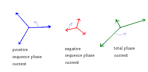 Notice that while the voltages were only 12% out of balance, the currents differ by almost a factor of three. Since the negative sequence voltages feed into an inductance which is one sixth of the inductance seen by the positive-sequence voltages, a rather modest imbalance in the voltages produces a totally unacceptable imbalance in the currents. In this example, the lead to the motor carrying the smallest current could be totally disconnected and it would not significantly change the performance of the motor. If a single motor is always run at a constant load, and the rotary phase converter and its associated capacitor bank are carefully adjusted, then it is possible to achieve better than a 12% voltage imbalance as discussed in the example above and get acceptable operation of the motor. The procedure would involve setting up the system of phase converter, motor and load; then measuring the generated voltages and the currents in each motor phase. If the current balance were unacceptable, then capacitors would need to be either added to, or taken out of the capacitor bank until the currents were balanced. In some cases, it might be necessary to switch to a different size phase converter to get the system balanced. If the motor were required to operate over a wide range of load conditions, or if several motors were powered using the same phase converter, it would be nearly impossible to get good voltage balance over the whole range of operation. If none of the motors were run at their full capacity, the job of getting everything to work properly would be easier. If the motor(s) were run at their full capacity for extended periods, such as in pumping applications, they would not tolerate voltage imbalance. In summary, phase imbalance adversely impacts both the performance and the life of a motor. Even modest voltage imbalance between the phases will require a motor to be de-rated as indicated in Table below. Phase imbalance will significantly reduce the life of motors that have a high duty cycle and operate at their maximum rated capacity.
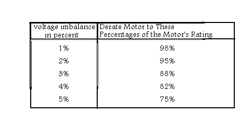
-
AuthorReplies
- You must be logged in to reply to this topic.