- This topic has 1 reply, 1 voice, and was last updated 4 years, 11 months ago by
حمید.
-
CreatorTopic
-
2021-08-03 at 11:08 am #448
محمد
در یک اینورتر توان بالا ترانزیستورهای قدرت(IGBT) موجود هر چند ماه یک بار میسوزند ،که با توجه به توان بالای دستگاه( 4MW) هزینه زیادی جهت تعویض آنها لازم است.
در یک اینورتر توان بالا ترانزیستورهای قدرت(IGBT) موجود هر چند ماه یک بار میسوزند ،که با توجه به توان بالای دستگاه( 4MW) هزینه زیادی جهت تعویض آنها لازم است.
چه دلایلی باعث سوختن ترانزیستورهای قدرت(IGBT) در یک سیستم INVERTER می گردد؟ -
CreatorTopic
-
AuthorReplies
-
2021-08-03 at 11:08 am #1855
همانطور که می دانید تجهیزات الکترونیکی عموماً از محدوده پایداری حرارتی مشخصی برخوردارند که کاربرد آنها را وابسته به شرایط بهره برداری می نماید. بنابراین لازم است دستورالعمل نصب سازنده اعم از حداکثر دمای محیط و محدودیت ارتفاع نصب که در عملکرد سیستم کولینگ دستگاه موثر است منظور شود. یکی از ویژگیهای IGBT که آنرا از ترانزیستورهای قدرت معمولی جدا می کند سرعت سوئیچینگ بسیار بالاتر آن است که به دلیل ساختمان ویژه آن حاصل شده است. پهنای باند پالسهای ایجاد شده توسط IGBT حدود 50 تا 150 نانو ثانیه است که بسیار کمتر از پهنای 2 تا 4 میکرو ثانیه مربوط به ترانزیستورهای قدرت است. این سرعت بالای IGBT ها و عملکرد مناسبشان به خاطر امپدانس بالای گیت ورودی سبب کاربرد وسیع آنها در اینورتر های توان بالا است. با این حال همین ویژگی مثبت گاهی می تواند سبب دردسر شود. برای مثال کابلهای ارتباطی بیش از 6 متر در فرکانس سوئیچینگ بسیار بالای مورد بحث می تواند سبب شکل گیری امواج ولتاژ مخرب در مدار شود که از سویی سیم پیچی الکترو موتور متصل به اینور تر را تهدید می کند و از سوی دیگر امواج انعکاسی از روی موتور می تواند سبب تخریب طبقه خروجی اینوتر یا ترانزیستورهای IGBT گردد. معمولاً برای کنترل چنین امواج خطرناکی در فواصل بیش از 20 فوت استفاده از فیلترهای ولتاژی در مدار حد فاصل اینورتر و موتور توصیه می شود. برای برخی اطلاعات مفید در خصوص مبحث مطرح شده می توان به موارد زیر توجه نمود.
A normal ac inverter has three parts: 1. An input converter to rectify ac power to dc power. It is normally called the source bridge. 2. An energy storage device which separates the input from the output and allows each to operate independently from the other. It is usually called a link filter. 3. A dc-to-ac inverter in the output stage. It is called an inverter. It generates the desired ac output voltage and frequency. Pulse-Width-Modulated Inverters (PWM) is referred to as time ratio control. From a constant dc input voltage, we get a variable output voltage and frequency by varying the percentage of time that the power control switch is closed. The output voltage will increase by increasing the percentage of time the switch is closed. The switch is either open or closed. There is no power dissipation across the switch in both states. 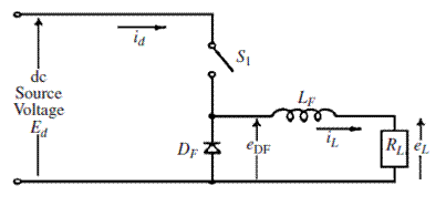 Below figure illustrates a typical two-level PWM inverter circuit. It is similar to the SCR bridge, but it uses IGBTs for the switching devices. The energy storage capacitor is denoted by C. The motor connections are a, b, and c. The inverter operation is as follows: Once the output frequency required to satisfy the speed regulator is given to the control system, it calculates the three-phase voltage commands. A triangle voltage waveform is generated and synchronized with the desired IGBT switching frequency and phase. This is the PWM carrier waveform that sets the basic inverter switching frequency. The average width of the PWM waveforms generated approximates the sine wave reference. The inductances average and smooth the resulting waveform.
 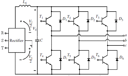 The IGBT is similar to the power transistor, except that it is controlled by the voltage applied to its gate rather than the current flowing into its base, as in power transistors. The current flowing in the gate of an IGBT is extremely small because the impedance of the control gate is very high. This device is equivalent to the combination of a metal-oxide semiconductor field effect transistor (MOSFET) and a power transistor (below Figure). Since the current required to control an IGBT is very small, it can be switched much more quickly than a power transistor. The IGBTs are normally used in high-power, high-frequency applications.
 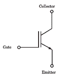 These bipolar power transistors are driven by an insulated gate metal-oxide transistor. A relatively simple 15-V gate driver signal is used to control the resulting high-current power transistor. The IGBT is a four-layer semiconductor similar to the SCR. Its main features are that 1. It has very fast switching on the order of 100 to 150 ns and resulting high-voltage transients dV/dt of 5000 to 10,000 V/?s. 2. The IGBT chips are soldered in place and connected with discrete bond wires. They are very weak when it comes to thermal fatigue problems. The IGBT modules have significantly lower thermal fatigue capability than other semiconductors. The high dV/dt generated leads to problems with bearing currents and the insulation system. Although thyristors, diodes, and IGBTs are solid-state devices, they have wear out mechanisms just as insulation and other mechanical parts do. The wear out and failure rates of these devices can be calculated. Common Failure Modes Differential Expansion (Mechanical Fatigue). This failure mode is mechanical fatigue or wear out caused by the difference in expansion rates as the temperature of the device changes. As the temperature of the device changes, different parts expand at different rates. These are the expansion coefficients for materials used in semiconductors:
 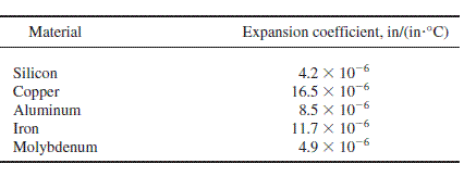 Thus, the parts slide over each other, causing mechanical wear out. This failure is common to all semiconductors. It normally occurs at the end of life of these devices. Below figure illustrates the general failure rate curve of SCRs, diodes, and IGBTs. The initial high failure rate is caused by manufacturing defects, application problems, and drive start-up stresses and lasts a few weeks. The high failure rate at the ends indicates the end of the life for the devices. In general, the lifetime of a device becomes shorter when it is operated harder and closer to its voltage rating.
  Fault Current Limit. This mode of failure is not applicable to IGBTs because they are not able to conduct currents in excess of their ratings. It is only applicable to thyristors and diodes GTOs. The junction temperature increases when the fault current increases. The maximum surge current that can be tolerated results in junction temperature excursion Tj of 300
 -
AuthorReplies
- You must be logged in to reply to this topic.