- This topic has 1 reply, 1 voice, and was last updated 2 years, 11 months ago by
.
-
Topic
-
Inside of an Electrical Room (ER) there are MV and LV equipments. Is it correct joining the ground bars of MV and LV circuits?
Inside of an Electrical Room (ER) there are MV and LV equipments. We use a Cu bar of 50x10to ground the LV circuits and another bar of 50×10 to ground the MV sistems. My design is that the LV ground bar do not be connected between them; each one must be connected directly at the earth mesh. But my customer wants to install a perimetrical bare cooper wire around the ER, and it must connect the LV ground bar and the MV ground bar. Is it correct??
Viewing 1 replies (of 1 total)
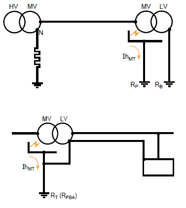 There are a good example in ” Practical Grounding, Bonding, Shielding and Surge Protection, G. Vijayaraghavan , Mark Brown , Malcolm Barnes ” text book which shown as following. Though it is theoretically possible to have a combined ground at the transformer for both MV and LV, such a practice may lead to unsafe conditions in the event of an MV to LV fault. Figure below shows the reason. The total impedance for a fault between HV and MV winding (neglecting the line impedance and the leakage impedance of the transformer windings) is the substation ground mat resistance of 10 ?, the NGR (neutral grounding resistance) value and the MV/LV combined ground electrode resistance assumed as 1 ?. For a 22-kV system (with line to ground voltage of 12 700 V) the current flow is: Ig = 12700/(35+10+1)= 276 A This gives a figure of 276 A. This current will cause the potential of 276 V to appear on the transformer tank and through the neutral lead to the enclosures of all equipment connected in the LV system with respect to true earth potential (this is because in TN-C-S type of systems, the neutral and equipment ground are one and the same). This value is unacceptably high. In actual practice, the line and transformer impedances come into play and the value will therefore get restricted to safe values. Use of combined MV and LV grounding is therefore possible only if the ground resistance can be maintained below 1 ?.
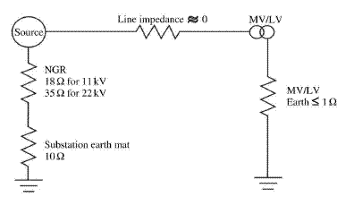
Viewing 1 replies (of 1 total)
- You must be logged in to reply to this topic.