- This topic has 3 replies, 1 voice, and was last updated 4 years, 8 months ago by
.
-
Topic
-
We have experienced unduly trips of a Stand By Earth Fault relay which uses the residual connection of the three phase CT's on primary side of 6.5 MVA 11/3.3KV Dyn11 transformer. …
We have experienced unduly trips of a Stand By Earth Fault relay which uses the residual connection of the three phase CT's on primary side of 6.5 MVA 11/3.3KV Dyn11 transformer.
We cannot increase the setting much as we will affect the coordination with upstream protections, we thus decided to insert a stabilizing resistor, the client agreed but wish to have the same settings as before but instantaneous, we think that the stabilizing resistor does not impose that and would prefer to strick to the actual settings with Io> using A VI curve and Io>> with 300 mSec delay. Can you pls advice?
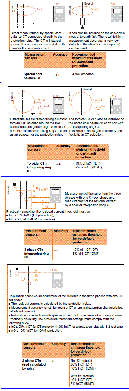 However ABB have some recommendation when we persist to application of low set earth fault protection in power system with high starting current. As ABB stated (1MRS 755627), the stabilizing resistor may be useful against huge starting current when the residual connection of the three phase CTs is used. Generally this connection is also called the Holmgreen connection. The residual connection can be used when the sensitivity requirement is about 10% of the CT nominal current, or higher. In this case an unwanted operation of the earth-fault protection relay sometimes occurs during motor or transformer start-up. The reason for the unwanted relay operation may be that the start-up current occasionally causes one or more of the three phase CTs in residual connection to saturate. The CT saturation is caused by the DC component of the unsymmetrical start-up current. To avoid this problem a suitable stabilizing resistor can be connected in series with the earth-fault current input of the protection relay. The stabilizing resistor forces the current fed by a non-saturated current transformer to flow through the secondary circuit of a saturated current transformer. Figure below illustrates the connection principle when the earth-fault current is measured through the residual connection of the three phase CTs. The stabilizing resistor is connected in series with the earth-fault current input of the protection relay. The purpose of the voltage-dependent resistor is to limit the voltage of the secondary circuit to a safe level. The need for a VDR is case-specific and can be checked by calculation.
 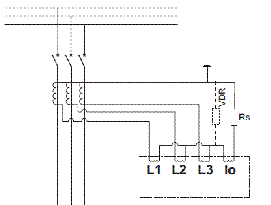 Calculation of stabilizing voltage The stabilizing voltage Us is calculated assuming that one of the residually connected current transformers will be fully saturated at motor start-up:
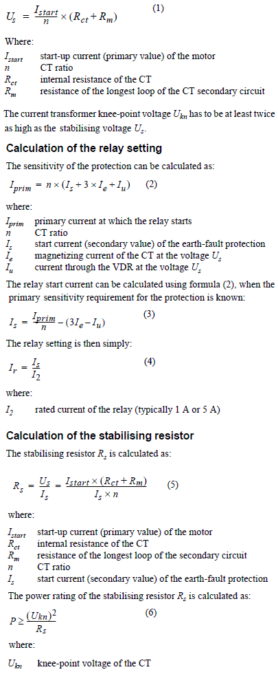
- You must be logged in to reply to this topic.