- This topic has 3 replies, 1 voice, and was last updated 4 years, 11 months ago by
.
-
Topic
-
من میخواهم یک کوره القایی درست کنم، بطوری که می دانیم کوره القایی را طوری درست می کردند که یک ژنراتور را با یک موتور سه فاز کوپل می کردند و در داخل کویل گرم کن جریان متغییر را به وجود می آوردند. …
من میخواهم یک کوره القایی درست کنم، بطوری که می دانیم کوره القایی را طوری درست می کردند که یک ژنراتور را با یک موتور سه فاز کوپل می کردند و در داخل کویل گرم کن جریان متغییر را به وجود می آوردند.
من هم ژنراتور را دارم و هم موتور سه فاز را ولی من نمی دونم که آنها را چه گونه با هم ارتباط بدهم و این ها را کوپل کنم. از شما خواهش دارم که مرا در این عرصه یاری کنید و یا توسط یک نقشه من را کمک کنید.
Viewing 3 replies - 1 through 3 (of 3 total)
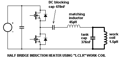 The inverter in this demonstration prototype was a simple half-bridge consisting of two MTW14N50 MOSFETs made my On-semiconductor (formerly Motorola.) It is fed from a smoothed DC supply with decoupling capacitor across the rails to support the AC current demands of the inverter. However, it should be realised that the quality and regulation of the power supply for induction heating applications is not critical. Full-wave rectified (but un-smoothed) mains can work as well as smoothed and regulated DC when it comes to heating metal, but peak currents are higher for the same average heating power. There are many arguments for keeping the size of the DC bus capacitor down to a minimum. In particular it improves the power factor of current drawn from the mains supply via a rectifier, and it also minimises stored energy in case of fault conditions within the inverter. The DC-blocking capacitor is used merely to stop the DC output from the half-bridge inverter from causing current flow through the work coil. It is sized sufficiently large that it does not take part in the impedance matching, and does not adversely effect the operation of the LCLR work coil arrangement. In high power designs it is common to use a full-bridge (H-bridge) of 4 or more switching devices. In such designs the matching inductance is usually split equally between the two bridge legs so that the drive voltage waveforms are balanced with respect to ground. The DC-blocking capacitor can also be eliminated if current mode control is used to ensure that no net DC flows between the bridge legs. (If both legs of the H-bridge can be controlled independently then there is scope for controlling power throughput using phase-shift control. See point 6 in the section below about “Power control methods” for further details.)
 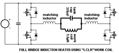 At still higher powers it is possible to use several seperate inverters effectively connected in parallel to meet the high load-current demands. However, the seperate inverters are not directly tied in parallel at the output terminals of their H-bridges. Each of the distributed inverters is connected to the remote work coil via its own pair of matching inductors which ensure that the total load is spread evenly among all of the inverters.
 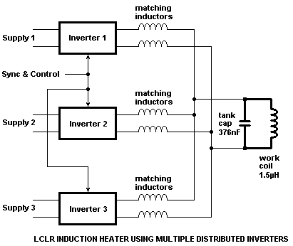 These matching inductors also provide a number of additional benefits when inverters are paralleled in this way. Firstly, the impedance BETWEEN any two inverter outputs is equal to twice the value of the matching inductance. This inductive impedance limits the “shoot between” current that flows between paralleled inverters if their switching instants are not perfectly synchronised. Secondly, this same inductive reactance between inverters limits the rate at which fault current rises if one of the inverters exhibits a device failure, potentially eliminating failure of further devices. Finally, since all distributed inverters are already connected via inductors, any additional inductance between the inverters merely adds to this impedance and only has the effect of slightly degrading current sharing. Therefore the distributed inverters for induction heating need not necessarily be located physically close to each other. If isolation transformers are included in the designs then they need not even run from the same supply.
Viewing 3 replies - 1 through 3 (of 3 total)
- You must be logged in to reply to this topic.