- This topic has 1 reply, 1 voice, and was last updated 4 years, 10 months ago by
حمید.
-
CreatorTopic
-
2021-08-03 at 11:08 am #873
رضا
طرز کار کلید حفاظت از جان (جریان نشتی) 3 پل چطور است؟
طرز کار کلید حفاظت از جان (جریان نشتی) 3 پل چطور است؟ -
CreatorTopic
-
AuthorReplies
-
2021-08-03 at 11:08 am #2823
کلیدهای حفاظت جان کلیدهایی هستند که ضمن آشکار سازی جریان خطرناک عبوری از بدن انسان ( 30 میلی آمپر) قبل از آنکه جریان مزبور خطر جدی برای سلامتی ایجاد کند منجر به قطع سیستم می شوند. در زیر مبانی اساسی طراحی وساخت چنین کلیدهایی را مشاهده می نمائید.
When a current exceeding 30 mA passes through a part of a human body, the person concerned is in serious danger if the current is not interrupted in a very short time. the protection of persons against electric shock in LV installations must be provided in conformity with appropriate national standards and statutory regulations, codes of practice, official guides and circulars, etc. Relevant IEC standards include: IEC 364, IEC 479-1, IEC 755, IEC 1008, IEC 1009 and IEC 947-2 appendix B. An electric shock is the pathophysiological effect of an electric current through the human body. Its passage affects essentially the circulatory and respiratory functions and sometimes results in serious burns. The degree of danger for the victim is a function of the magnitude of the current, the parts of the body through which the current passes, and the duration of current flow. IEC Publication 479-1 defines four zones of current-magnitude/time-duration, in each of which the pathophysiological effects are described. 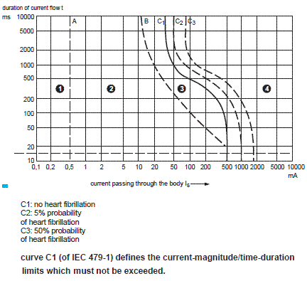 Any person coming into contact with live metal risks an electric shock. Curve C1 shows that when a current greater than 30 mA passes through a part of a human being, the person concerned is likely to be killed, unless the current is interrupted in a relatively short time. The point 500 ms/100 mA close to the curve C1 corresponds to a probability of heart fibrillation of the order of 0.14%. The protection of persons against electric shock in LV installations must be provided in conformity with appropriate national standards and statutory regulations, codes of practice, official guides and circulars, etc. Relevant IEC standards include: IEC 364, IEC 479-1, IEC 755, IEC 1008, IEC 1009 and IEC 947-2 appendix B. In figure below the method TN-C is shown, in which the neutral conductor acts as both the Protective-Earth and Neutral (PEN) conductor. In all TN arrangements, any insulation fault to earth constitutes a phase-neutral short-circuit. High fault current levels simplify protection requirements but can give rise to touch voltages exceeding 50% of the phase-to neutral voltage at the fault position during the brief disconnection time. In practice, therefore, earth electrodes are normally installed at intervals along the neutral of the supply network, while the consumer is generally required to install an earth electrode at the service position. On large installations additional earth electrodes dispersed around the premises are often provided, in order to reduce the touch voltage as much as possible. In high-rise apartment blocks, all extraneous conductive parts are connected to the protective conductor at each level. In order to ensure adequate protection, the earth fault current Id = Uo/ Zs or 0.8 Uo/ Zc > Ia where Uo = nominal phase-neutral voltage. Zs = earth-fault current loop impedance, equal to the sum of the impedances of: the source, the live phase conductors to the fault position, the protective conductors from the fault position back to the source. Zc = the faulty-circuit loop impedance. Note: the path through earth electrodes back to the source will have (generally) much higher impedance values than those listed above, and need not be considered. Id = the fault current. Ia = a current equal to the value required to operate the protective device in the time specified.
 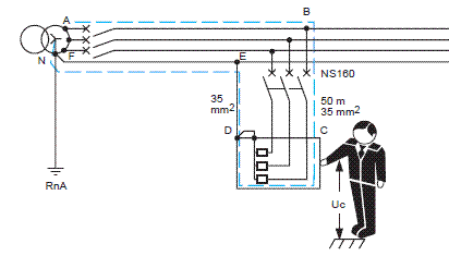 The essential features of ELCB are shown diagrammatically in figure below. A magnetic core encompasses all the current carrying conductors of an electric circuit and the magnetic flux generated in the core will depend at every instant on the arithmetical sum of the currents; the currents passing in one direction being considered as positive, while those passing in the opposite direction will be negative. In a normally healthy circuit i1 + i2 = 0 and there will be no flux in the magnetic core, and zero e.m.f. in its coil. An earth-fault current id will pass through the core to the fault, but will return to the source via the earth, or via protective conductors in a TN earthed system. The current balance in the conductors passing through the magnetic core therefore no longer exists, and the difference gives rise to a magnetic flux in the core. The difference current is known as the “residual” current and the principle is referred to as the “differential current” principle. The resultant alternating flux in the core induces an e.m.f. in its coil, so that a current i3 flows in the tripping-device operating coil. If the residual current exceeds the value required to operate the tripping device, then the associated circuit breaker will trip.
 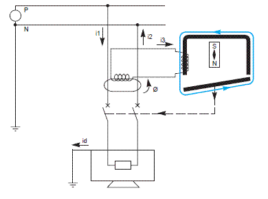 These devices are commonly incorporated in the following components: – industrial-type moulded-case differential circuit breakers conforming to IEC 947-2 and its appendix B, – domestic-type differential circuit breakers (RCCBs)* conforming to IEC 755, 1008, and 1009 (RCBOs), – differential switches conforming to particular national standards, – relays with separate toroidal (ring-type) current transformers, conforming to IEC 755. RCDs are mandatorily used at the origin of TT-earthed installations, where their ability to discriminate with other RCDs allows selective tripping, thereby ensuring the level of service continuity required.
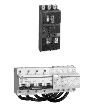
-
AuthorReplies
- You must be logged in to reply to this topic.