- This topic has 1 reply, 1 voice, and was last updated 2 years, 11 months ago by
.
-
Topic
-
Please guide for the protection scheme of transformer with four winding.
following transformer specifications, …
Please guide for the protection scheme of transformer with four winding.
following transformer specifications, …Transformer MVA:63MVA
Transformer primary side voltage:220 kv(star connection with neutral solid ground)
Transformer secondary side voltage for winding-1:6.9 kv(star connection with neutral resistive ground)
Transformer secondary side voltage for winding-2:6.9 kv(star connection with neutral resistive ground)
Transformer secondary side voltage for winding-3:6.9 kv(open delta with ground connection).
This is not an auto transformer.
Transformer application: This transformer is used to take power supply from the 220kv grid and to feed the station load at the generating station when generators are not in runing condition.In normal condition when generator are running , this transformer is remains in almost at vary low load condition. This transformer is uni-directional power supply( from 220 kv to 6.9 kv system). This is only step down transformer and used to supply load.Is it possible to provide the REF protection on the 220 kv side of the transformer(star connection with neutral solid ground) for above said transformer?
Also when fault occurs on 220 kv winding which protection will protect the winding? pl explain with diagram.
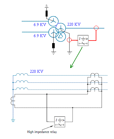 The degree of protection is very much improved by the application of restricted earth fault protection (or REF protection). This is a unit protection scheme for one winding of the transformer. It can be of the high impedance type as shown in Figure above, or of the biased low impedance type. For the high-impedance type, the residual current of three line current transformers is balanced against the output of a current transformer in the neutral conductor. In the biased low-impedance version, the three phase currents and the neutral current become the bias inputs to a differential element. The system is operative for faults within the region between current transformers, that is, for faults on the star winding in question. The system will remain stable for all faults outside this zone. The gain in protection performance comes not only from using an instantaneous relay with a low setting, but also because the whole fault current is measured, not merely the transformed component in the HV primary winding (if the star winding is a secondary winding). Hence, although the prospective current level decreases as fault positions progressively nearer the neutral end of the winding are considered, the square law which controls the primary line current is not applicable, and with a low effective setting, a large percentage of the winding can be covered. Restricted earth fault protection is often applied even when the neutral is solidly earthed. Since fault current then remains at a high value even to the last turn of the winding, virtually complete cover for earth faults is obtained. This is an improvement compared with the performance of systems that do not measure the neutral conductor current. Earth fault protection applied to a delta-connected or unearthed star winding is inherently restricted, since no zero sequence components can be transmitted through the transformer to the other windings. Both windings of a transformer can be protected separately with restricted earth fault protection, thereby providing high-speed protection against earth faults for the whole transformer with relatively simple equipment. A high impedance relay is used, giving fast operation and phase fault stability.
 - You must be logged in to reply to this topic.